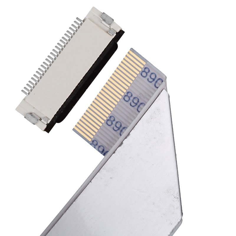
Contact terminals: They are usually made of high conductivity and high strength alloy materials such as phosphor bronze, and are plated with gold to enhance conductivity and corrosion resistance. The terminal is responsible for achieving electrical connection between the FPC gold finger and the PCB, requiring low contact resistance (generally ≤ 20m Ω) to ensure signal integrity.
Insulation shell (rubber shell): made of engineering plastics with high temperature resistance and insulation performance such as LCP (liquid crystal polymer), PA9T or PPS, used to fix terminals and provide electrical isolation. It has an equidistant barrier structure inside to ensure neat terminal arrangement and prevent short circuits.
Locking mechanism: There are two common types: flip type (ZIF, zero insertion force) and slide in type (non ZIF). The flip cover compresses the FPC cable by pressing the cover plate, reducing damage during insertion and removal; The sliding in type relies on an elastic structure to achieve self-locking, which is suitable for high-frequency plugging and unplugging scenarios.
Solder End Piece: Used to firmly solder FPC connectors onto PCBs, it is available in two methods: Surface Mount Technology (SMT) and Through Hole Installation (THT), which affect the stability and spatial layout of the connection.